PRODUCT COMPLIES WITH THE STANDARD PN-EN 12566-3+A2:2013-10
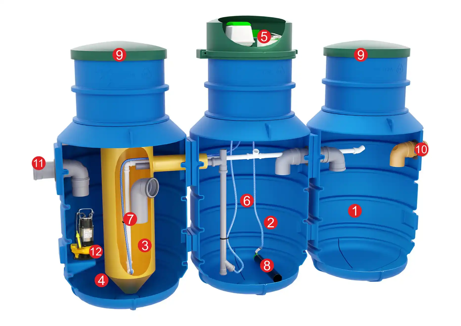
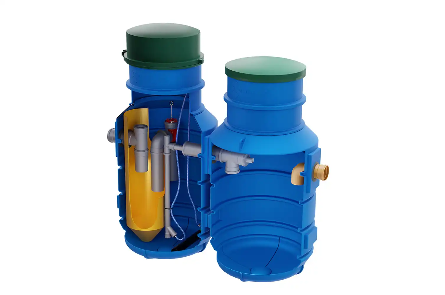
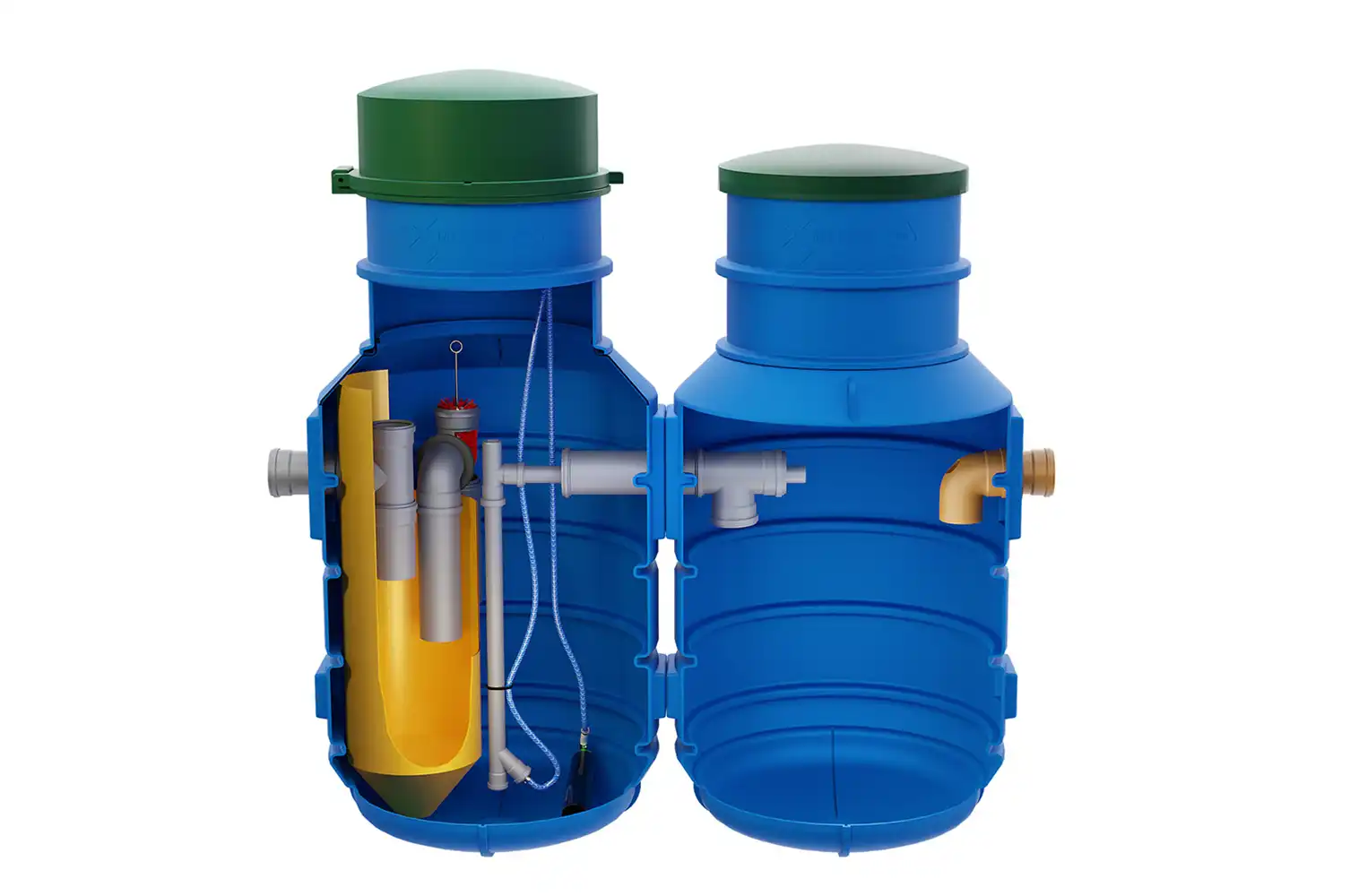
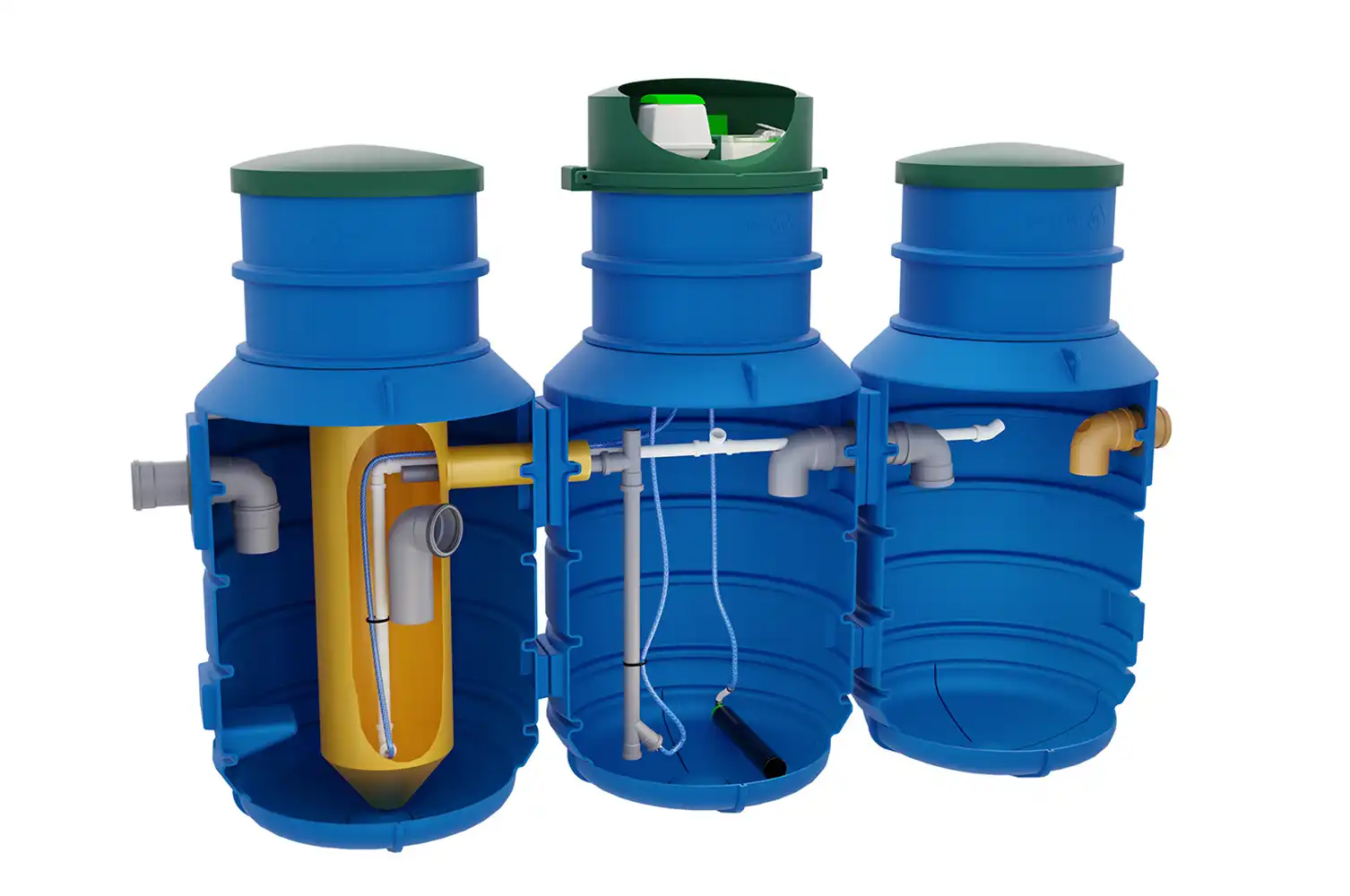
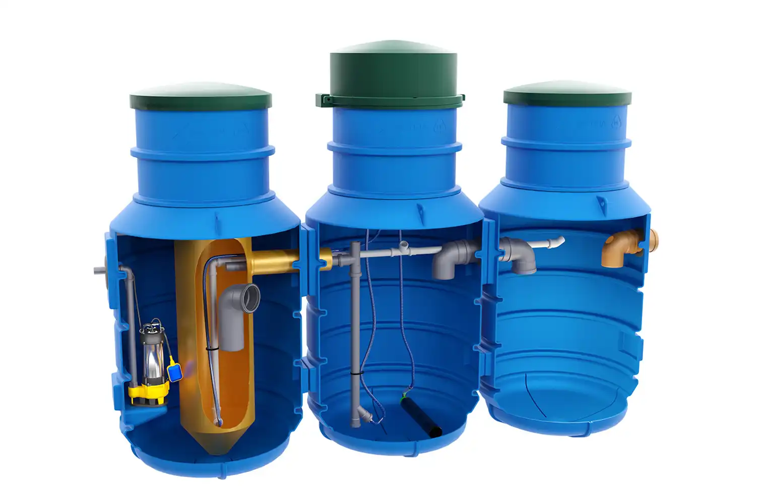
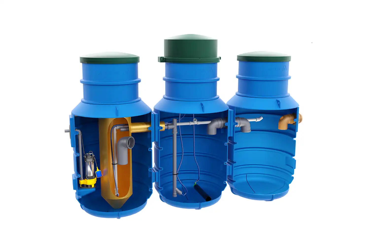
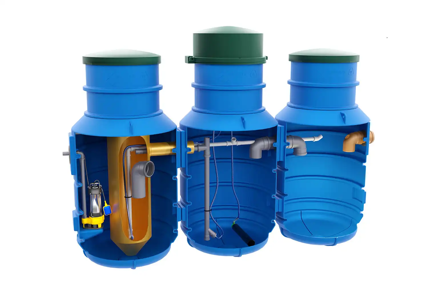
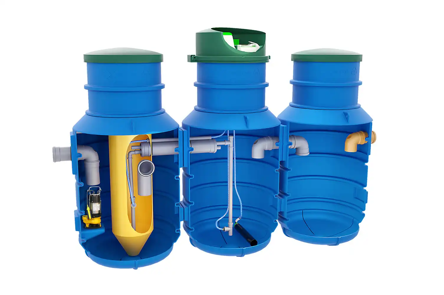
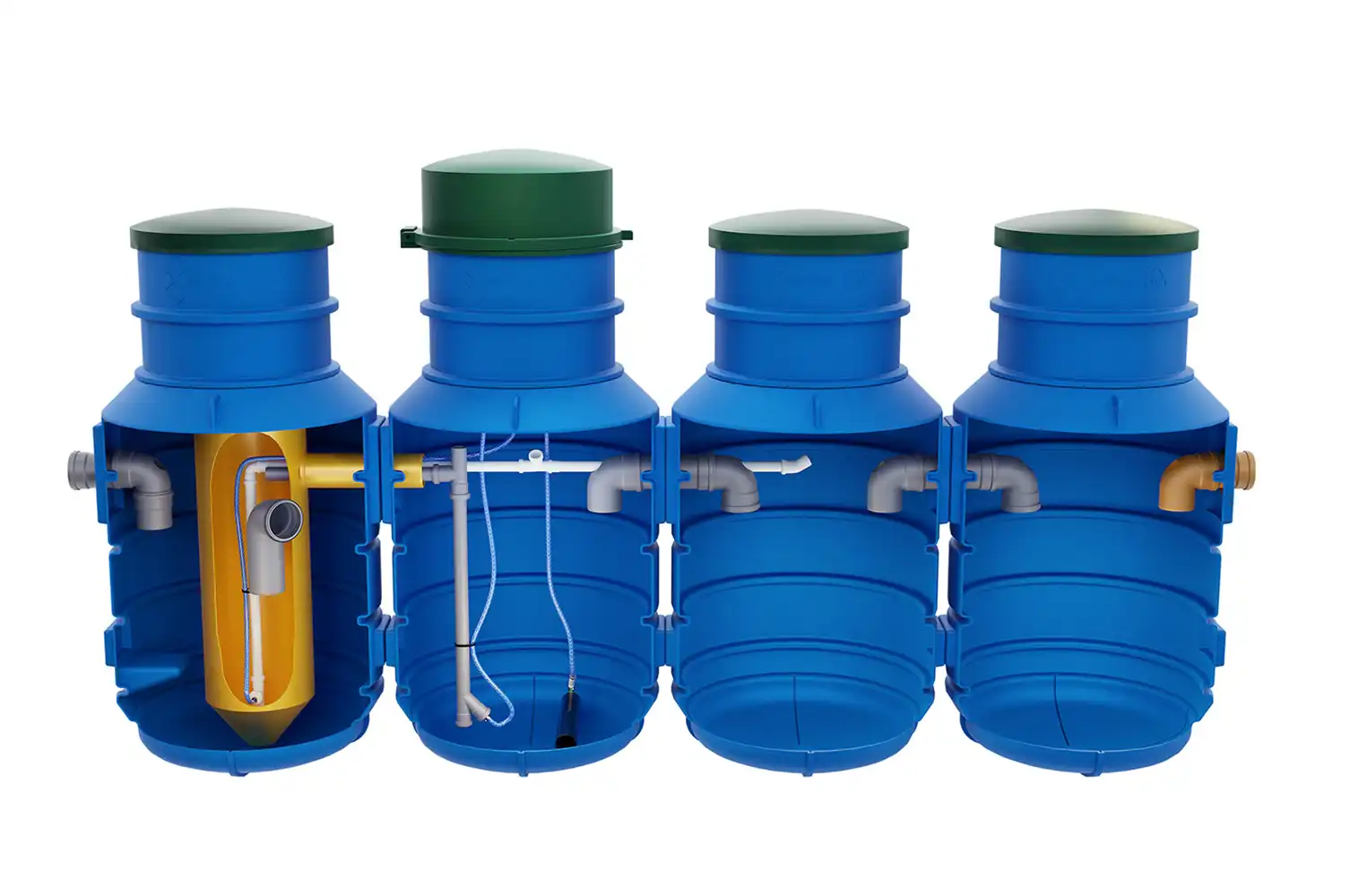
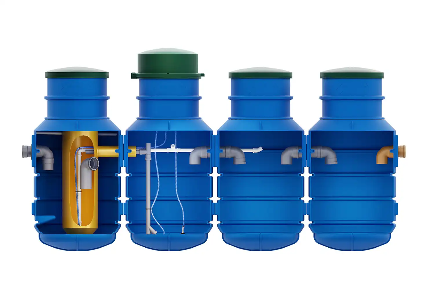
Built-in pumping station for treated sewage (option 2)
Treated sewage outlet DN110 (option 1)
Raw sewage inlet DN160
Sediment tank covers
Sediment tank covers
Aeration diffuser
Pompa mamutowa recyrkulacji
Mammoth recirculation pump
Pompa mamutowa
Control module
Secondary settling tank
Imhoff's Funnel
Biological reactor
Primary settling tank
PureFlow Diagram
- Primary settling tank
- Biological Reactor
- Imhoff Cone
- Secondary settling tank
- Control module
- Mammoth Pump
- Recirculation Airlift Pump
- Aeration Diffuser
- Settler Covers
- Raw sewage inlet DN160
- Treated sewage outlet DN110
- Built-in Treated Wastewater Pumping Station


DESTINY
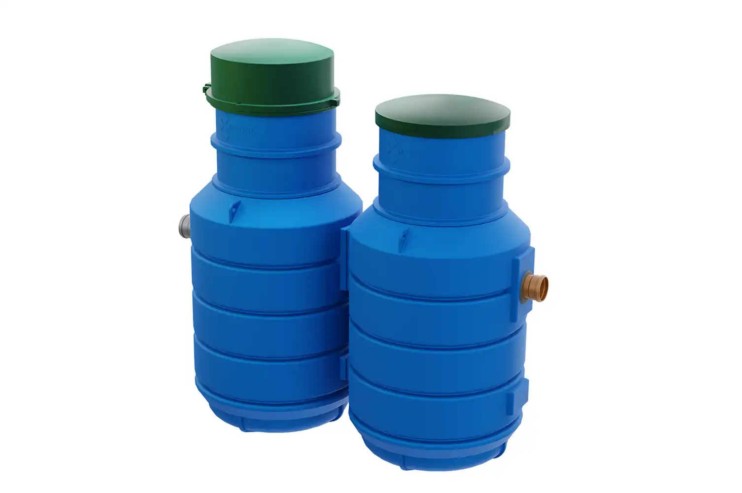
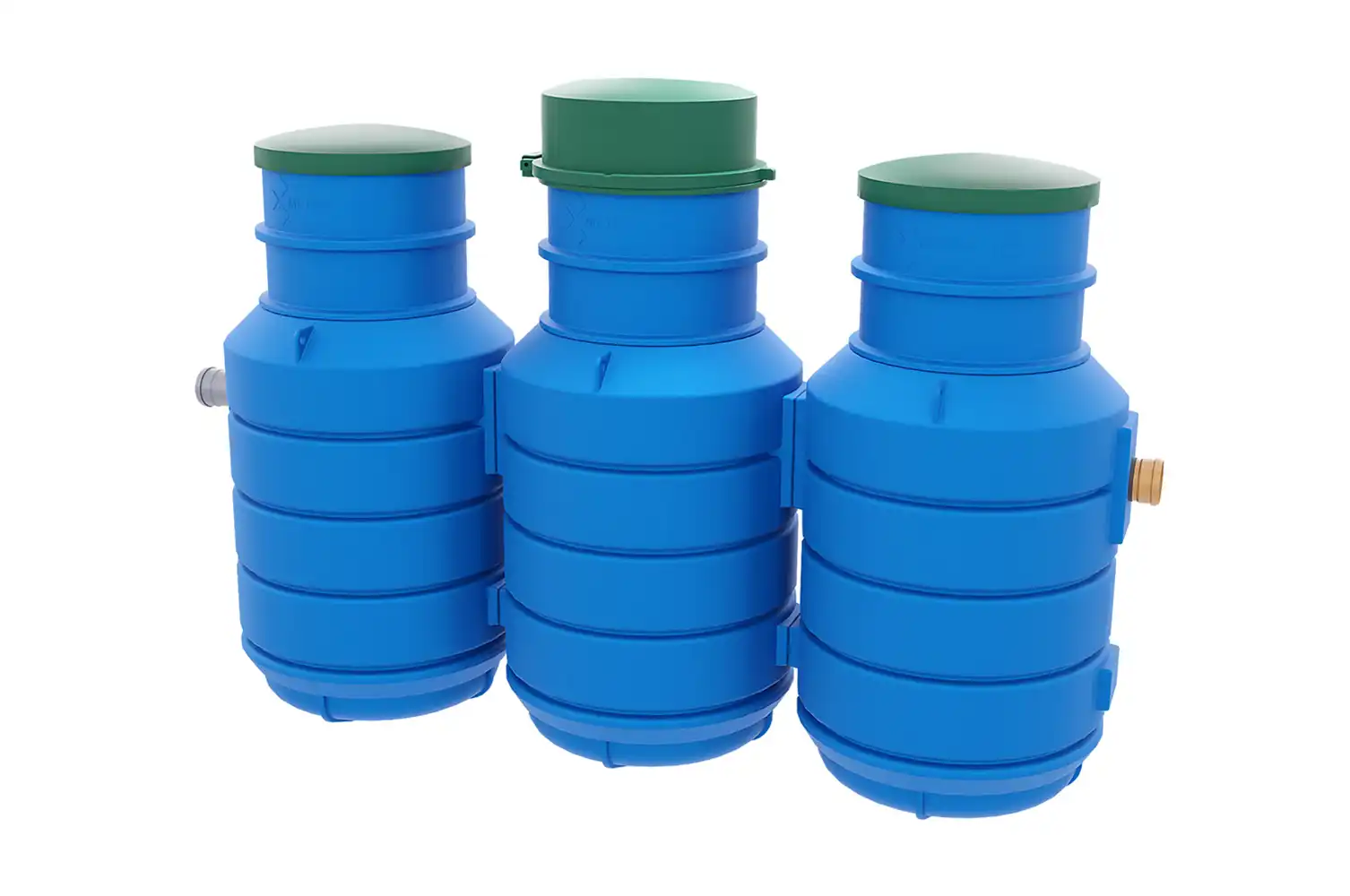
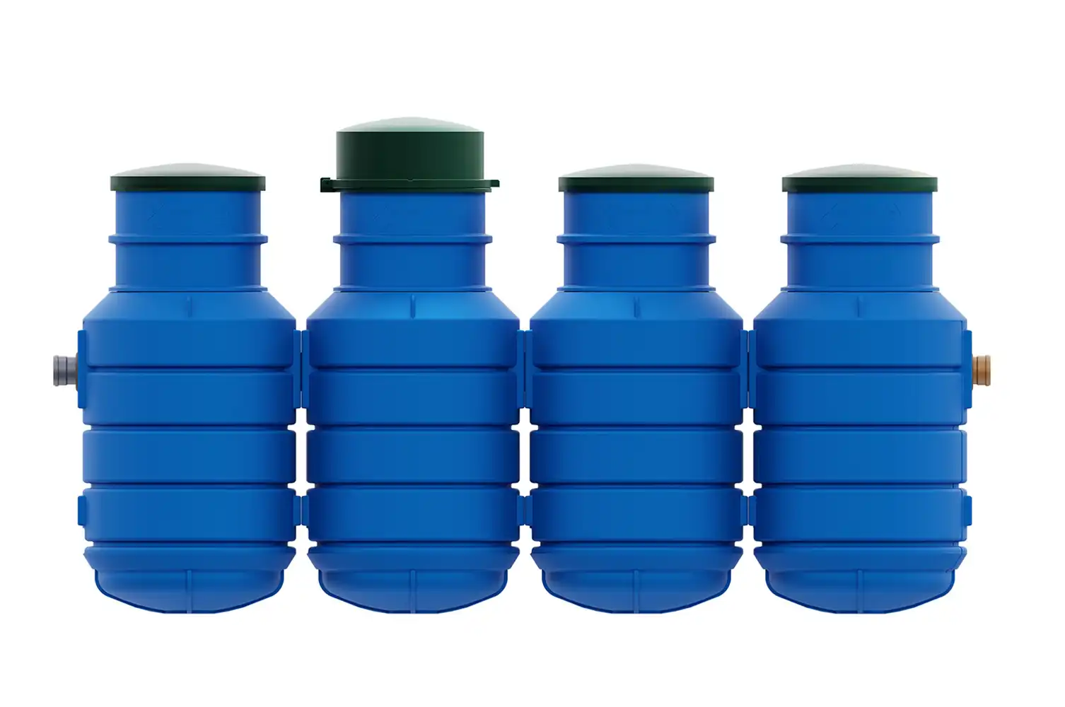
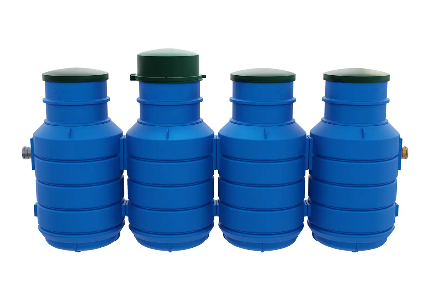
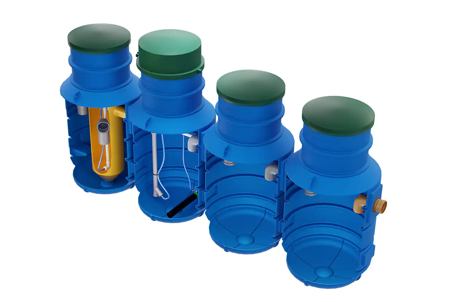
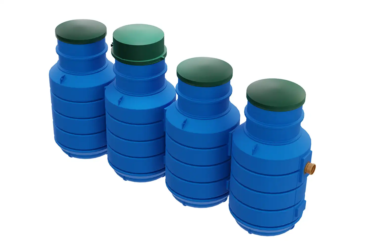
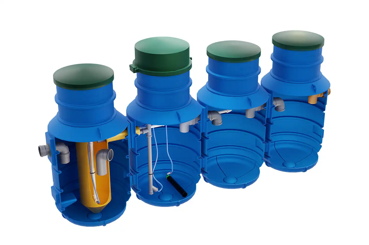
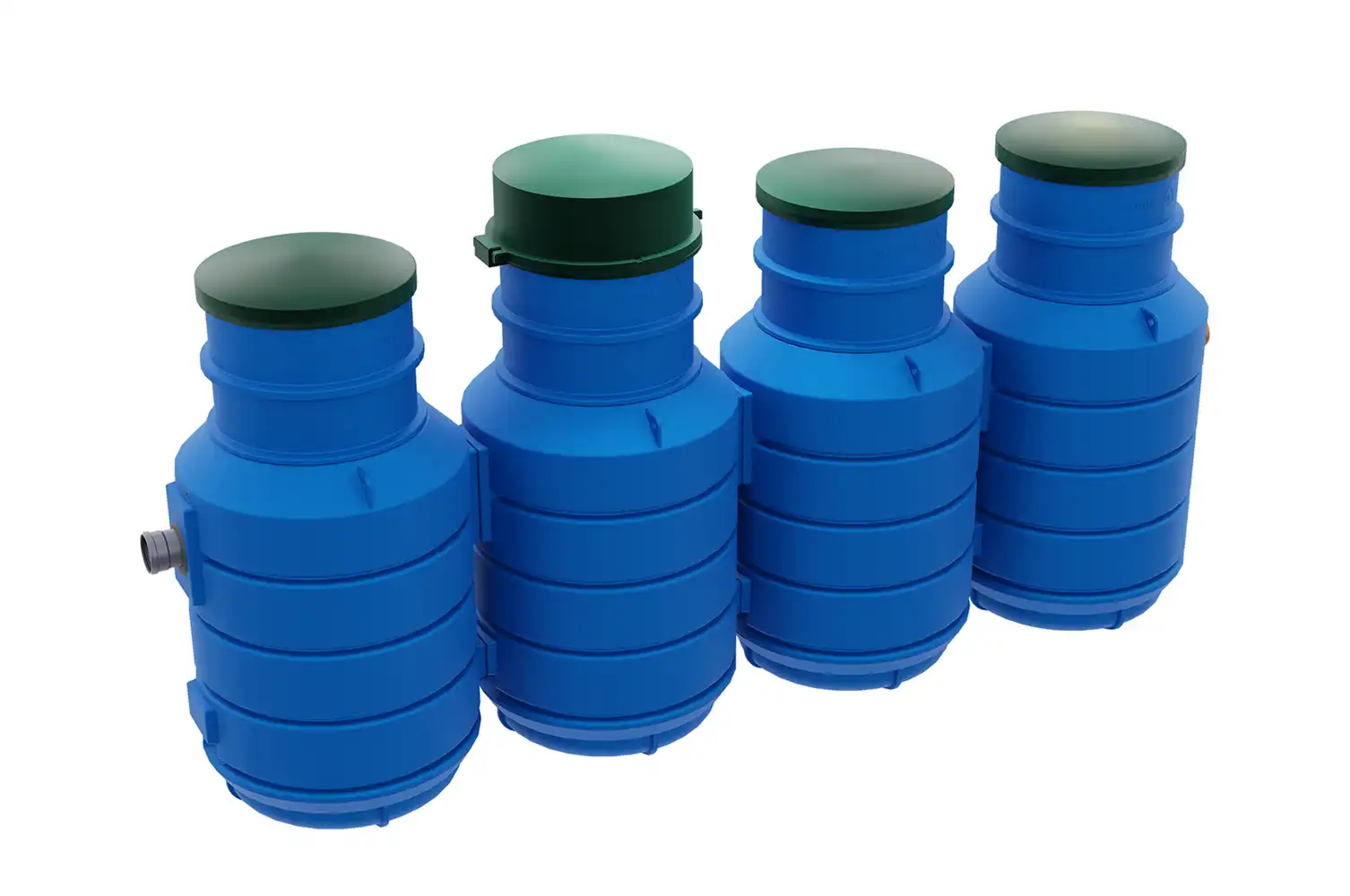
The PureFlow biological wastewater treatment plant is designed for treating domestic wastewater in areas without access to sewage systems. The use of activated sludge technology – identical to that used in wastewater treatment plants serving entire cities – allows for very good parameters of treated wastewater. This solution, used for years, has gained recognition worldwide as effective and simple in construction. Appropriately ribbed, vertical tanks allow for maximum space utilization and optimal conditions for the growth of bacteria necessary in the treatment process. The simple construction without solenoid valves and controllers helps avoid expensive servicing; it’s enough to check the valve settings once or twice a year. By default, the treatment plant consists of three chambers. The primary settler is where raw sewage from the household flows in. This is where the pollutant load is averaged and mechanical treatment occurs. Sediments heavier than water settle to the bottom and undergo partial mineralization, fats collect at the top forming a scum layer, and the wastewater in between flows to the second tank. In the biological reactor, proper wastewater treatment takes place. Thanks to intensive aeration, bacterial microflora develops, which breaks down the pollutants contained in the wastewater. Then, the treated wastewater flows into the Imhoff cone, where it is deprived of bacterial suspension – activated sludge. It is recirculated to the biological reactor. Then, the pre-clarified liquid flows to the secondary settler where final sedimentation occurs. Despite its simplicity, the PureFlow biological treatment plant excellently handles domestic pollutants, and the construction enriched with an additional secondary settler ensures clear and transparent effluent at the outflow. This means that the treatment plant can optionally be equipped with a treated wastewater pump, which allows saving a lot of money and space necessary for building a classic pumping station. In summary, the PureFlow treatment plant is a simple and effective solution for all water and soil conditions and is an excellent choice for your home.
DESCRIPTION OF THE OPERATION OF THE PureFlow DOMESTIC SEWAGE TREATMENT PLANT
PHASE I – RAW SEWAGE INFLOW:
PHASE II – AERATION IN THE BIOLOGICAL REACTOR:
PHASE III – SEDIMENTATION
PHASE IV – FINAL CLARIFICATION AND DISCHARGE OF TREATMENT WASTEWATER:
HOLIDAY MODE
WASTEWATER TREATMENT EQUIPMENT
TYPE OF WASTEWATER TREATMENT PLANT

Treatment plants must be transported in a horizontal position (inspection chimneys positioned vertically) and must be properly secured with securing straps. The customer/buyer should participate in unloading – the device should be inspected. Care should be taken when moving the tank. The treatment plant should be lifted using a rope or sling passed through the handles attached to the tank, or from below using a forklift. The tank should be carefully lifted from the delivery vehicle and placed on level ground. Do not roll the treatment plant off the delivery vehicle.
Tanks must not be thrown and should not be dragged on the ground. In the upper part of the treatment plant there are handles to which securing straps can be attached.
When choosing the installation location, the type of soil and groundwater level should be determined, as soil conditions will have a significant impact on determining the type of backfill and installation conditions. When planning the installation location, remember to ensure access for service vehicles during installation and later operation.


Furthermore, the distance of the clarifier, which comprises the domestic wastewater treatment plant (for single-family, farm, and individual recreational buildings) from the property boundary and public road should be a minimum of 2 m. From windows and external doors to rooms intended for permanent human occupancy, the distance should be no less than 5 m (in direct proximity to single-family buildings). The location distance of filtration ditches and drainage fields should be 30 m from wells, 2 m from the neighboring property boundary, road (street) or pedestrian walkway. A domestic treatment plant can be built in direct proximity to single-family buildings, provided its ventilation is routed through the sewage system at least 0.6 m above the upper edge of windows and external doors in these buildings.

An important criterion determining the location of a domestic wastewater treatment plant is the distance from water intakes. The treatment plant tank should not be installed at a distance less than 15 m from the nearest well. The distance of the infiltration drainage from water intakes should be at least 30 m, and the groundwater level must be at a depth of 1.5 m below the treated water discharge system. Maintaining such distances is conditioned by the possibility of pathogenic microorganisms penetrating water intakes. Importantly, the above distances apply to all water wells intended for human consumption – both on the property where the domestic wastewater treatment plant is to be located and on neighboring properties.

An important condition for using infiltration drainage is having soil with appropriate permeability and groundwater occurrence at least 1.5 m below the planned position of the wastewater infiltration drainage. Otherwise, it may be necessary to install a sewage pumping station and construct drainage in the form of an embankment.
Note! The treatment plant should be located in non-vehicular terrain with access for sewage trucks.
INSTALLATION OF THE HDPE SETTLER
General rules
To maintain the good condition of the appliance and its operation, follow this instruction manual and its attachments. Incorrect installation may affect the improper operation of the treatment plant. The excavation and installation of the treatment plant should be carried out by a specialized contractor.
Never enter an unventilated tank – LIFE HAZARD!
Make sure that the ground around the treatment plant does not have factors that may have a negative impact during and after installation (guarantee a stable position, keep a safe distance from buildings).
Do not work in heavy rainfall (risk of trench collapse).
Soil subsidence must be taken into account in all assembly work.
After installing the tank and after each service inspection, check that the inspection hatches are closed and properly protected against opening.
We make a trench for a clarifier with dimensions in a floor plan 0.5 – 1.0 m larger than the dimensions of the settling tank. The minimum width of the backfill is 50 cm on each side of the tank.
We make sand ballast with a thickness of min. 30 cm and thicken to at least 85% (according to the Proctor scale).
We lower the tank into the trench, level and make the first layer of 30 cm of sand backfill in order to stabilize it and compact it to min. 85% according to the Proctor scale.
Check the position of the aeration diffusers. They should lie flat on the bottom of the tank.
After leveling and stabilizing the tank, we make backfilling in layers every 30 cm with its simultaneous compaction to the level of the drain spigot according to the proportions and degree of compaction as above. In each layer of filling, the clarifier should be filled with water to the level of backfilling. Particular attention must be paid to the thorough filling of all the cavities of the tank with material and the strong compaction of the layers, so that there are no voids in the backfill, which will guarantee the stability of the tank.
After making the backfill and compacting it, connect the inlet and drain ports, connecting it simultaneously with the distribution manhole.
We install the DN 650 extension, adjusting the height to the expected level of the ground (terrain) and finish the backfill with compaction. When installing the extension, it is imperative to seal the connection point with a special tank designed for this purpose with glue (e.g. Wurth glue + sealant) or another suitable sealant and then screw it with screws (e.g. Farmer type). The tank cover should not exceed 120 cm.
After the installation of the clarifier is completed, a leak test must be carried out.
After completing the above-mentioned works, we proceed to the installation of the drainage.
10. After the excavation is made, depending on the type of soil, we make a protective layer with simultaneous installation of drainage pipes and, if necessary, a supporting layer and covering it with geotextile.
After installing the device and putting it into operation, it is very important to check the correct arrangement of the diffusers located in the biological treatment zone. The biological reactor hatch must be opened and, if necessary, the diffuser should be lifted and laid flat on the bottom, which will ensure that the wastewater is aerated evenly.
Compliance with the manufacturer's guidelines will ensure the stability and functionality of the treatment plant tank and its proper behavior in the trench. Slight deformations of the tank result from the properties of the material used and do not affect the proper operation of the treatment plant. A deformation of the tank of not more than 5% is allowed.


- installation depth 55 - 110 cm
- maximum line length - 24.0 m
- distance between lines 1.0 - 3.0 m depending on soil category
- drainage slope 0.5 - 1.0%
- excavation width at bottom min. 0.5 m
- groundwater level min. 1.5 m below drainage bottom

INSTALLATION VENTILATION
- To ensure proper operation of the treatment plant, the building should have high ventilation of at least DN 110 as sewerage ventilation.
- The outlet of the ventilation pipe removing vapors should be routed above the building roof.
- Ventilation should run in a straight line, without bends or constrictions, taking into account and sealing all inspection objects to enable proper and effective operation.
- In case of installing the system at a greater distance from the building, or in case of lack of high ventilation in the building, additional ventilation should be installed on the building facade and routed to a height of at least 50 cm above the roof ridge.
- If installing additional external ventilation on a residential building is impossible for various reasons, neighboring buildings or other structures should be used.
- Infiltration drainage should be ventilated using an exhaust vent at the end of each drainage line - so-called low ventilation.

The safe design of the device has been achieved by eliminating moving parts. Therefore, BDH construction does not use electric pumps, and the monolithic tank made of polyethylene (PE) ensures device tightness.
The BDH biological treatment plant has CE marking – It has been tested by a notified testing body for compliance with PN-EN 12566-3+A2:2013-10 – therefore our treatment plants provide high treatment efficiency confirmed by tests.
Low sensitivity to power supply interruptions – In case of power failure, the control system adapts treatment phases to the amount of wastewater flowing to the treatment plant and activates the appropriate phase depending on accumulated wastewater.
The treatment process is automated – Allowing control over the treatment cycle, additionally the control system automatically adapts to the amount of wastewater inflow.
Ability to set the treatment plant to standby mode – Allows maintaining the treatment process even without wastewater inflow for up to 2 weeks.
Easy and inexpensive expansion – Thanks to modular construction, expansion involves adding an additional tank without the need to replace all treatment plant components.
Treatment in the BDH biological wastewater treatment plant occurs without the need for biopreparations.
Long service life and reliability – PE tanks are made monolithically, additionally reinforced inside the tank with steel reinforcement.
The treatment plant does not require a large land area for installation.
The tanks of the BDH biological treatment plant and their internal components are 100% recyclable for used products and raw material reuse.
The device is energy-efficient – allows saving money and protecting the environment.
By treating wastewater, we protect the valuable resource that is water.
- Single and multi-family homes,
- Holiday resorts,
- Small businesses

PureFlow 4
PureFlow 6
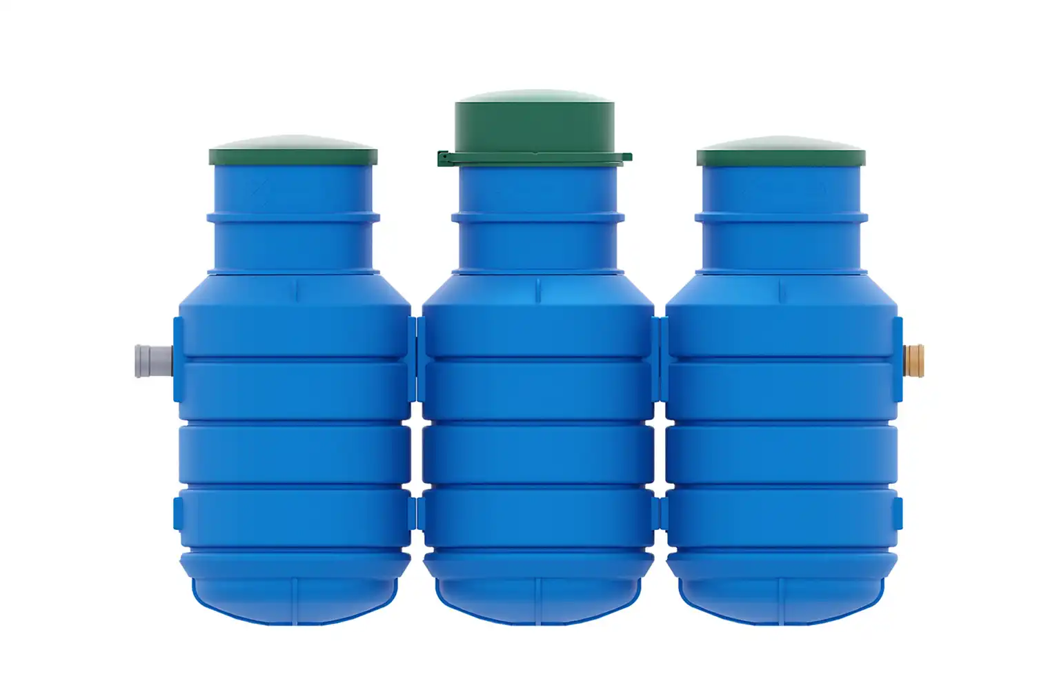
PureFlow 8
Pure Flow product data
Rotomolding Products
- RotoClean biological home sewage treatment plant
- Domestic Biological Wastewater Treatment Plant SBR
- BDH Biological Domestic Wastewater Treatment Plant
- Biological Domestic Wastewater Treatment Plant Soft SBR
- PureFlow Biological Domestic Wastewater Treatment Plant
- EKO OG Domestic Wastewater Treatment Plant
- Domestic Wastewater Treatment Plant B.1, B.1.5
- Domestic Wastewater Treatment Plant B.2, B.3, B.4
- Domestic wastewater treatment plant P.3, P.4, P.5, P.6
- Nolen Wastewater Treatment Plant Accessories
- Septic Tanks – Plastic Cesspools
- Diesel and AdBlue tanks – Nolen AdON 5 and AdON 9
- 1000 Litre Nolen Fuel Tank
- 1500 Litre Nolen Fuel Tank
- Fuel tank 1500 B Liters Nolen
- 2500 Liter Fuel Tank Nolen
- 2500B Liters Nolen Fuel Tank
- 5000 Litre Nolen Fuel Tank
- 9000 Litre Nolen Fuel Tank
- Liquid fertilizer tanks (RSM)
- 250L fuel tank – mobile
- 460L fuel tank – mobile
- 600L fuel tank – mobile
- Accessories for diesel tanks
- Rainwater tanks EKO OG 2.0, 3.0, 4.0
- Rainwater tanks B.1, B.1.5
- Rainwater tanks B.2, B.3, B.4
- Rainwater tanks P.3, P.4, P.5, P.6